How Jet Engines Work: The Physics of Flight Power
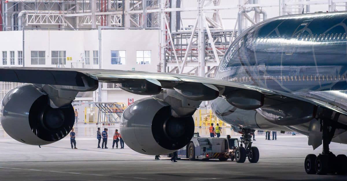
Photo: Peter Xie / Pexels
The GE90-115B engine on a Boeing 777 is rated at 115,300 pounds-force of takeoff thrust, or about 513 kilonewtons. Its fan, the big disk you see from the terminal window, is 128 inches (3.25 meters) across and carries 22 carbon-fiber blades. Inside the hot section, the gas can be hotter than the melting point of the nickel alloy that holds it in. The engine survives because its blades are cast as single crystals, hollowed out, and bathed in cooling air. Follow the air from intake to nozzle and the rest makes sense.
Key takeaways
- Every jet engine produces thrust by Newton's third law: it throws mass backward, and the reaction pushes the aircraft forward.
- The engine core runs a Brayton cycle: compress the air, add heat by burning fuel, then expand the gas through a turbine that drives the compressor.
- Modern airliners use turbofans, which route most of the air around the core. Moving a lot of air a little faster wastes less energy than moving a little air very fast.
- Bypass ratio, the ratio of bypass airflow to core airflow, rose from 0.3 in the first production turbofan to roughly 9 to 12 in current designs.
- Turbine blades survive gas hotter than their own melting range through single-crystal casting, internal cooling, film cooling, and ceramic coatings.
The principle: Newton explains most of it
A jet engine is a machine for pushing air backward. That sounds too simple, but it is the whole job. NASA's Glenn Research Center puts it directly: the thrust an engine generates depends on the mass flow through the engine and the exit velocity of the gas, and it follows from Newton's third law of motion (NASA Glenn, Beginner's Guide to Aeronautics).
Think of a swimmer pushing off the pool wall. The wall does not push on its own. The swimmer shoves, and the wall's reaction shoves back. An engine does the same thing with air: it grabs the air in front, speeds it up, and ejects it behind. The faster or the heavier the stream of ejected air, the harder the reaction.
The simplified thrust equation is F = ṁ × (V_exit − V_flight), where F is thrust, ṁ is the mass of air passing through per second, V_exit is the speed of the exhaust jet, and V_flight is the speed of the aircraft. The real equation also carries terms for the fuel mass added and for pressure differences at the nozzle, but this version captures the logic. Thrust grows if you move more air or if you speed it up more.
That gives an engine designer two knobs, and the choice between them shapes every airliner flying today.
Why a jet engine is not a rocket
A rocket carries both its fuel and its oxidizer, so it can run in a vacuum. A jet engine carries only fuel. It borrows oxygen from the surrounding atmosphere, which is why NASA notes that most of the exhaust mass in a turbine engine comes from the air itself, and why such engines cannot work in space.
This has a practical side effect. A jet engine's thrust depends on how much air it can gulp, so thrust falls as the aircraft climbs into thinner air. For more on the rocket side of the story, see the explainer on how rocket engines actually work.
The Brayton cycle: squeeze, burn, expand
Every gas turbine engine runs a thermodynamic loop called the Brayton cycle. The idea is easy to state: compress air, add heat to it at constant pressure, then let it expand and extract work. If the work you get out of the expansion exceeds the work you spent on the compression, you have a net surplus to spend on thrust.
An analogy helps. Pump up a bicycle tire and the pump barrel gets warm, because compressing air heats it. Now imagine that after compressing the air, you could heat it even further for free by burning fuel in it, and then let it push a windmill. The windmill would spin much harder than the pump needed to turn, because hot gas expands with far more force than cold gas compresses. A jet engine is that bicycle pump, a flame, and a windmill, all on one shaft.
Step 1: Compression
Rotating compressor stages push the incoming air into a smaller and smaller space. Each stage is a ring of rotating blades followed by a ring of stationary vanes, and each adds a modest pressure boost. Stacked together, the effect is dramatic. Published overall pressure ratios, which compare combustor pressure to ambient pressure, run roughly as follows for current large engines:
| Engine | Overall pressure ratio |
|---|---|
| GE90-115B | 42:1 |
| CFM LEAP | 40:1 (50:1 at top of climb) |
| Rolls-Royce Trent XWB | 50:1 |
| GE9X | 60:1 |
Sources: engine specification tables compiled on the Wikipedia pages for the GE90, LEAP, Trent XWB, and GE9X, as of 2026.
Compression heats the air as a side effect. By the time it reaches the combustor, the air is already hot, before any fuel has been added.
Step 2: Combustion
Kerosene-based jet fuel is sprayed into the combustor as a fine mist and ignited. The flame in a modern engine is not a Bunsen burner. It burns continuously, held in place by carefully shaped airflow, and the combustor is wrapped in a flow of cooler air so the metal liner does not melt. Much of the air going through the combustor does not burn fuel at all. It dilutes and cools the gas before the gas reaches the turbine.
Burning fuel at constant pressure raises the temperature, and with it the gas's ability to expand. Engineers want the highest turbine inlet temperature the materials can tolerate, because a hotter cycle extracts more work per kilogram of air.
Step 3: Expansion through the turbine
The hot, high-pressure gas rushes through the turbine, a set of blade rows that look like a compressor running backward. The gas pushes on the blades, the turbine shaft spins, and that shaft drives the compressor and, in a turbofan, the fan.
In an engine with a large fan, the turbine takes a great deal of the gas's energy to turn the fan. The leftover pressure and heat leave through the nozzle as a fast jet. That remaining jet is the part of the thrust that the core produces directly.
Step 4: The nozzle
The exhaust nozzle shapes and accelerates the stream leaving the engine. On many modern airliners, the core and bypass flows leave through separate concentric nozzles. The choice of nozzle shape trades noise, weight, and efficiency, and it is one of the places where designers tune an engine to its aircraft.
Turbojet to turbofan: why airliners moved the air around the core
Early jet engines were turbojets. All of the air entered the core, and all of it left as a hot, fast jet. That is excellent for supersonic fighters, but it wastes energy at subsonic speeds. To see why, run the numbers on two imaginary engines.
A worked example: same thrust, different waste
Suppose an aircraft cruises at 250 meters per second (about 900 kilometers per hour), and two engines each need to produce 20 kilonewtons of thrust. These numbers are illustrative and use the simplified thrust equation above, ignoring fuel mass and nozzle pressure terms.
| Engine A (turbojet-like) | Engine B (high-bypass-like) | |
|---|---|---|
| Air mass flow | 50 kg/s | 200 kg/s |
| Speed gain of the air | 400 m/s | 100 m/s |
| Jet speed | 650 m/s | 350 m/s |
| Thrust (flow × speed gain) | 20 kN | 20 kN |
| Useful power (thrust × flight speed) | 5.0 MW | 5.0 MW |
| Kinetic energy left in the jet | 4.0 MW | 1.0 MW |
| Propulsive efficiency | 56% | 83% |
Both engines push the aircraft equally hard. Engine A burns fuel to hurl a small mass of air very fast, and it leaves 4 megawatts of kinetic energy in the wake, where it does nothing for the aircraft. Engine B moves four times as much air only a quarter as fast, and wastes a quarter as much energy.
The shortcut formula for this is propulsive efficiency = 2 / (1 + V_jet / V_flight). A jet that leaves much faster than the aircraft flies wastes energy. A jet that leaves only a little faster than the aircraft flies wastes little. That is the formula quoted in the Wikipedia turbofan article, and it matches the table above (2 / (1 + 650/250) = 0.56, and 2 / (1 + 350/250) = 0.83).
An analogy: a rowing boat. You can move it with a small, fast paddle that churns up a lot of water, or with a large, slow oar that moves a lot of water gently. The oar is the more efficient way to turn effort into boat speed, because less of your energy ends up in swirling water behind you. A turbofan's fan is the large oar.
The bypass ratio
A turbofan puts a large fan at the front, driven by the core's turbine. Some of the fan's air goes into the core. Most of it goes around the core through a duct and leaves at the back. The ratio of the bypass air to the core air is the bypass ratio. As the turbofan article puts it, a bypass ratio of 6 means six times more air passes through the bypass duct than through the core.
The first production turbofan, the Rolls-Royce Conway, had a bypass ratio of 0.3. An earlier German turbofan design, the Daimler-Benz DB 670, ran only on a test bed, with its first run on May 27, 1943. Today's large engines sit at much higher ratios:
| Engine (aircraft) | Bypass ratio | Fan diameter | Thrust |
|---|---|---|---|
| Rolls-Royce Conway (early production turbofan) | 0.3 | not listed | not listed |
| CFM LEAP-1B (Boeing 737 MAX) | 9:1 | 69.4 in (176 cm) | 100–130 kN |
| GE90-115B (Boeing 777) | 9 | 128 in (3.25 m) | about 513 kN |
| Rolls-Royce Trent XWB (Airbus A350) | 9.6:1 | about 3.0 m | 375–431 kN |
| GE9X (Boeing 777X) | 10:1 | 134 in (3.40 m) | 489 kN (base rating) |
| Pratt & Whitney PW1100G (Airbus A320neo) | about 12:1 | not listed | not listed |
Sources: Wikipedia engine pages cited above and the PW1000G page; the Turbofan page for the Conway and DB 670. Figures are as published as of 2026, and manufacturers' ratings vary by variant.
How much of the thrust comes from the fan? The turbofan article states that cool, slow bypass air yields between 30 and 70 percent of the total thrust of a turbofan system. The share rises with bypass ratio, and in the highest-bypass engines the fan produces most of the thrust.
Why not make the fan even bigger?
Fans cannot grow forever. A bigger fan makes the engine heavier, adds drag from the larger nacelle, and eventually runs into ground clearance under the wing. There is also a mismatch problem: the turbine that drives the fan runs best at high rotational speed, while a very large fan needs to turn slowly, because its blade tips would otherwise approach supersonic speeds and get noisy and inefficient.
Two solutions have emerged. One is composite blades, which are light enough to let the fan grow without the engine becoming impractical. The GE90's 22 carbon-fiber fan blades are a case in point: according to the specifications compiled on the GE90 page, these provide double the strength at one-third the weight of traditional titanium fan blades, and the engine uses far fewer blades than the older CF6's 38 despite a fan about 30 inches larger.
The other solution is a gearbox.
The geared turbofan
Pratt & Whitney's PW1000G family puts a 3:1 gearbox between the fan and the low-pressure shaft. The fan turns at roughly 4,000 to 5,000 revolutions per minute, while the low-pressure compressor and turbine spin at 12,000 to 15,000. Each part runs near its own best speed.
Pratt & Whitney claims about 16 percent better fuel efficiency than previous-generation engines, and the first commercial delivery, an Airbus A320neo to Lufthansa, took place on January 20, 2016. The same design has also had a real-world setback. In July 2023, Pratt & Whitney ordered inspections of roughly 1,200 of about 3,000 PW1100G engines after contaminated powdered metal was found in some parts, and in September 2023 the inspection was expanded to all of them. Each inspection takes 250 to 300 days, according to the PW1000G page. New engine architectures buy efficiency, but they also add new ways to fail.
Inside a modern turbofan: the CFM LEAP-1B
The best way to understand an engine is to count its stages. The LEAP-1B, which powers the Boeing 737 MAX, has the layout below, according to the LEAP specification page. It entered revenue service in May 2017.
| Section | What it has | What it does |
|---|---|---|
| Fan | 1 stage, 18 composite blades, 69.4 in (176 cm) diameter | Pushes air through the bypass duct and feeds the core |
| Low-pressure compressor (booster) | 3 stages | First squeeze of the air entering the core |
| High-pressure compressor | 10 stages | Takes air to an overall pressure ratio of about 40:1 |
| Combustor | Annular ring with fuel nozzles | Burns fuel at constant pressure |
| High-pressure turbine | 2 stages | Drives the high-pressure compressor |
| Low-pressure turbine | 5 stages | Drives the fan and booster through the low-pressure shaft |
The LEAP family is claimed to burn about 15 percent less fuel than the CFM56 it replaced, a family-wide figure from the manufacturer. Its cruise thrust-specific fuel consumption, the pounds of fuel burned per hour for each pound of thrust, is listed at 0.53. For comparison, the Trent XWB-84 is listed at 0.478.
Two shafts carry the turbine's work forward. The high-pressure turbine and compressor spin together on one, and the low-pressure turbine, booster, and fan on another, running concentrically. That arrangement lets each spool settle at its own speed, much as the two gears of a bicycle let your legs and the rear wheel work at different rates.
Materials: surviving gas hotter than the metal
Compressing and burning air to a high temperature improves efficiency, so engine makers push the temperature as high as materials allow, and then past it. The Wikipedia page on turbine blades notes that the gas flowing past the blades is typically in the range of 1,300 to 1,800 kelvins, which can exceed the melting point of the blade material (about 1,300 to 1,400 kelvins). The blades do not melt because they are actively cooled. Here is how.
Single-crystal superalloys
A normal metal casting is made of many tiny crystals, called grains, packed together. At high temperature and high stress, the boundaries between grains are the weak points, because atoms slip and cracks start there. A single-crystal blade is cast as one crystal, so there are no grain boundaries at all. The blade is cast so that a specific crystal direction, written as the ⟨001⟩ direction, runs along its length. The turbine blade article describes single-crystal blades as ideal for first-stage and second-stage turbine blades, and notes that high-cycle fatigue (the repeated vibration of the blade) is the leading cause of single-crystal blade failure.
Internal cooling and film cooling
The blade is hollow, threaded with passages that carry cooler air bled from the compressor. Serpentine paths and small fins inside the passages increase surface area, so the air picks up heat efficiently. In the places with the heaviest heat load, such as the leading edge, jets of air are aimed at the inner wall.
Then the air goes out through tiny holes in the blade surface and forms a thin film that insulates the outer surface from the hot gas. According to the turbine blade article, cooling air uses about one to three percent of the main flow and can lower blade metal temperature by 200 to 300 degrees Celsius. That is a real cost: air bled for cooling does not make thrust. Cooling design is a balancing act between protecting the blade and wasting air.
Ceramic coatings and composites
A thin ceramic thermal barrier coating on the blade surface acts as insulation. First-generation coatings appeared in the 1970s, and ceramic coatings improved through the 1980s, increasing blade temperature capability by roughly 90 degrees Celsius (200 degrees Fahrenheit), according to the turbine blade page.
The next step is to replace metal in the hottest parts with ceramic matrix composites. On the GE9X, ceramic matrix composites are used in the combustor liners, nozzles, and first-stage high-pressure turbine shroud, and they run about 260 degrees Celsius (500 degrees Fahrenheit) hotter than nickel alloys. The LEAP also uses ceramic matrix composites for its turbine shrouds, which are lighter than those of the CFM56.
The gas flowing through the hot section of a modern engine can exceed the melting point of the blade metal. Cooling air, taken from the compressor, is what keeps the blades solid. Every kilogram of air used for cooling is a kilogram that does not push the aircraft.
How the jet engine got here
The idea of a gas turbine for propulsion is older than the first working engines. Frank Whittle patented his design in 1930, and his experimental engine began test runs on April 12, 1937. The Gloster E.28/39, powered by a Whittle W.1 engine, took off from Cranwell on May 15, 1941. In Germany, Hans von Ohain's work led to the Heinkel He 178, the first flyable jet aircraft, which flew in 1939. The two engineers worked independently, on opposite sides of a war, which is the story told in the article on the invention of the jet engine.
The jump from those engines to today's airliners took decades of incremental change: higher pressure ratios, hotter turbines, better materials, and finally large fans. The arrival of the commercial jet changed global travel, a story covered in the jet airliner, and the broader sweep of aviation history runs from the Wright brothers' first flights to today's twin-engine long-haul aircraft.
What can go wrong, and how engines are certified for it
Jet engines are designed on the assumption that things will fly into them and that parts will eventually fail. Regulators write those assumptions into law.
Bird strikes
In the United States, 14 CFR 33.76 sets the bird ingestion tests that a new engine must pass (14 CFR 33.76 at Cornell LII). The tests depend on inlet size:
| Test | Details (summarized from the regulation) |
|---|---|
| Large single bird | One bird aimed at the most critical spot on the first-stage rotor, ingested at 200 knots. Weight depends on inlet area: at least 1.85 kg (4.07 lb) for inlets under 1.35 m², 2.75 kg (6.05 lb) for 1.35 to under 3.90 m², and 3.65 kg (8.03 lb) at 3.90 m² and above |
| Small flocking birds | 85 g (0.187 lb) birds, one per 0.032 m² of inlet area, up to 16 |
| Large flocking birds | Applies at inlet areas of 2.50 m² or more. Bird weights run from 1.85 kg to 2.50 kg depending on inlet size |
For the large flocking bird test, thrust must not sustain a drop below 50 percent of maximum rated takeoff thrust during the run-on, and the engine must not shut down. For small and medium birds, a sustained thrust loss above 25 percent is not acceptable. The rules do not promise that an engine is unharmed. They promise that it fails safely.
Compressor stalls and flameouts
A compressor blade is a small wing. If the airflow over it separates, as a wing does when it stalls, the compressor can no longer push air against the pressure behind it. The result can be a compressor stall, in which airflow through the engine breaks down and thrust drops. Ingesting a flock of birds, volcanic ash, or heavy ice can trigger one, as can bad airflow at the intake. Pilots can often restart a flamed-out engine in flight, because the windmilling of the fan keeps the compressor turning.
Containment
Fan blades and turbine disks store huge amounts of rotational energy. Certification therefore requires engines to contain a failed blade inside the casing, so that debris does not pierce the fuselage or the fuel tanks. Engine cases and fan containment systems are heavy for exactly this reason.
Why jet engines make contrails, and what that does to the climate
The water vapor in jet exhaust, one of the products of burning hydrogen-containing kerosene, can condense and freeze in the cold upper atmosphere, forming ice-crystal trails. Whether those trails vanish in seconds or spread into long-lived cirrus-like cloud depends mostly on how humid the air is at altitude.
The climate effect of those clouds is large. In a 2021 assessment of global aviation's contribution to climate forcing, Lee and colleagues estimated the 2018 effective radiative forcing from contrail cirrus at 57.4 milliwatts per square meter, compared with 34.3 for aviation's carbon dioxide, and 100.9 for the net total (Lee et al., 2021, via PubMed Central). They found that non-CO₂ effects together accounted for 66 percent of aviation's net effective radiative forcing in 2018. The uncertainty is large: the 5 to 95 percent likelihood range for the net total spans 55 to 145 milliwatts per square meter. The study measures radiative forcing, not total warming from a flight, but the finding is why the aviation industry is now looking at contrails as well as at carbon dioxide.
Contrails also form only under particular atmospheric conditions. That means flight planning could in principle avoid the small fraction of airspace where persistent contrails form, an idea that is still being studied.
Can jet engines run on sustainable fuel?
Sustainable aviation fuels, or SAF, are made from sources such as waste oils, agricultural residues, or synthesis from hydrogen and carbon dioxide. They are designed to be chemically close to conventional jet fuel, so existing engines can burn them. Under the ASTM D7566 standard, most approved production pathways can be blended with conventional jet fuel at up to 50 percent. Reported lifecycle emission reductions vary widely by feedstock and method, from a few tens of percent to well over 90 percent in some published estimates.
The main constraint is supply. SAF production in 2023 was about 600 million liters, roughly 0.2 percent of global jet fuel use according to the Wikipedia summary of SAF, with some sources putting it lower. Engines are not the bottleneck. Fuel production is.
What people get wrong about jet engines
"The engine pulls the plane." The fan and compressor do pull air in, but the thrust that moves the aircraft is the reaction to accelerating that air backward. The pressure inside the engine does the pushing.
"Jet engines are inefficient because they burn so much fuel." Per unit of thrust and per passenger-kilometer, modern high-bypass engines are far more efficient than the early turbojets. The propulsive efficiency numbers above show why: a larger, slower stream of air wastes less energy. Total fuel burn is large because aircraft are large and heavy.
"A hotter engine is always a better engine." Higher temperatures raise efficiency, but they also cost cooling air, demand exotic materials, and shorten the life of hot-section parts. Engine design is a compromise between thermodynamics and metallurgy.
"More thrust always means more speed." Thrust is a force, not a speed. An engine rated at 513 kilonewtons does not push an aircraft faster than one rated at 100 kilonewtons by that ratio, because drag rises steeply with speed and heavier aircraft need the extra force just to climb and accelerate.
For a related look at how aircraft structures handle pressure and stress, see why airplane windows are rounded. Readers curious about the extreme end of machinery can compare the engines here with the entries in the most powerful machines ever built. And the thermodynamics behind the Brayton cycle fits into a bigger picture in how thermodynamics explains everything.
FAQ
Q: What happens if a bird flies into a jet engine? A: Engines must pass certification tests in which birds are fired into them. Under 14 CFR 33.76, a single large bird of 1.85 to 3.65 kilograms (depending on inlet size) is ingested at 200 knots, and flocks of smaller birds are tested too. The standard is a safe failure, not an undamaged engine: blades must be contained, and for flock tests thrust must not fall below set limits. Larger or multiple strikes can still cause compressor stalls or flameouts.
Q: How do jet engines start? A: A starter, usually driven by compressed air from a ground cart, an auxiliary power unit, or another running engine, spins the compressor until enough air flows through the core. Fuel and ignition are then added. Once combustion is self-sustaining, the turbine takes over the job of driving the compressor and the starter disengages. The sequence takes a minute or two on a typical airliner.
Q: Why do jet engines make contrails? A: Water vapor in the exhaust condenses and freezes in the cold upper air, forming ice crystals. Whether the trail persists depends mainly on how humid the surrounding air is. Persistent contrails can spread into cirrus-like clouds. A 2021 assessment by Lee and colleagues estimated that contrail cirrus had an effective radiative forcing of 57.4 milliwatts per square meter in 2018, larger than the 34.3 estimated for aviation's CO₂.
Q: Can jet engines run on sustainable fuels? A: Yes, within limits. Sustainable aviation fuels made from waste oils, residues, or synthesized from hydrogen and CO₂ are approved for blending with conventional jet fuel, generally up to 50 percent under ASTM D7566 for most pathways. Lifecycle emission savings depend heavily on the feedstock. Supply is the constraint: about 600 million liters were produced in 2023, a small share of global jet fuel use.
Q: What is the difference between a turbofan, a turboprop, and a turboshaft? A: All three use a gas turbine core. A turbofan uses the core to drive a ducted fan and produces thrust from both the fan and the core exhaust. A turboprop uses the core to turn a propeller through a gearbox, and it produces little thrust from its own exhaust. A turboshaft delivers nearly all of its power as shaft power, with no useful exhaust thrust, and is used in helicopters, ships, and power generation.
Q: Why do modern engines have such big fans? A: A bigger fan raises the bypass ratio, which means moving more air at lower speed for the same thrust. Per the propulsive efficiency formula, 2 / (1 + V_jet / V_flight), a slower jet wastes less energy. The limits are weight, nacelle drag, ground clearance, and the fact that very large fans must turn slowly while turbines run fastest at high speed, which is why geared designs exist.
The takeaway
A jet engine looks complicated, but its logic fits in one sentence: raise the pressure of air, add heat, and extract more work from the expansion than the compression cost. Everything else in the hardware serves that loop. The turbofan was a change of emphasis rather than of principle, spending the core's energy to move much more air much more gently, which is why a 9:1 or 12:1 bypass ratio beats a turbojet at airliner speeds.
What limits engines now is mostly materials and manufacturing. Gas hotter than the blade alloy, ceramic parts running 260 degrees Celsius hotter than nickel, and the powder-metal quality problems that grounded part of the PW1100G fleet all point the same way. The physics has been settled for decades. The work is in building parts that survive it.
Sources
- NASA Glenn Research Center, Beginner's Guide to Aeronautics: Turbine Engines
- U.S. Code of Federal Regulations, 14 CFR 33.76, Bird ingestion
- Lee, D. S. et al. (2021), contribution of global aviation to anthropogenic climate forcing for 2000 to 2018, PubMed Central PMC7468346
- Engine specification tables: GE90, GE9X, CFM LEAP, Trent XWB, PW1000G, Turbofan, Turbine blade, Frank Whittle
Read next:
Follow new articles
Add SciHub101 to your feed reader to see new science and technology stories.
About the Author
SciHub101 is an independent science and technology publication founded and edited by Buğra Sözeri, a software engineer and app developer based in Türkiye. AI tools assist with drafting and research. Source documentation in the existing archive is uneven, and articles are being reviewed and corrected. The Editorial Team byline identifies editorial responsibility; it does not certify specialist or independent human review. Where we compare products, anything built by our own team is labelled as such — see the editorial guidelines and About page for how corrections and disclosures work.
Related Articles

How Vaccines Were Invented: The History That Saved Hundreds of Millions of Lives
From smallpox to COVID-19, vaccines are humanity's most powerful medical technology. Here's how we discovered them.
History of Electricity: Faraday, Tesla, Edison, and the Force That Powers the World
Electricity was a scientific curiosity in 1800. Within 100 years it was lighting cities and running factories.
How Airplanes Fly — Physics of Flight
The real physics behind lift, thrust, and drag — what every textbook gets wrong and what actually keeps 400-ton jets in the sky.
History of Aviation: From the Wright Brothers to Today
On December 17, 1903, Orville Wright flew 120 feet in 12 seconds. In 2024, airlines carried about 4.7 billion passengers. Here is how the engineering got from one to the other.

How Satellites Orbit Earth: The Physics and Engineering Behind Eyes in the Sky
There are over 8,000 active satellites orbiting Earth right now. Here's how they stay up and what they do.
How Fiber Optic Cables Transmit Data
A strand of glass thinner than a human hair can carry more information than all the copper wires ever made. Here's the physics behind it.